青岛大志美德电气有限公司是一家以节能降碳为依托,专注于能源管理系统方案的研发、设计、制造、销售及增值服务为一体的高新技术企业,作为节能增效解决方案商,公司拥有完整的产品线及解决方案,并设有专业能源设计与评估团队,为用能单位进行“能源审计、能源评估、节能建议、项目实施”一站式服务,帮助用能单位应对能源双控、支撑双碳转型。公司产品主要涉及六大系统:智能动照系统、能源管理系统、智能环控系统、中央空调制冷机房节能群控系统、高效机房智能管控系统、超洁净环境控制系统等。
大志美德已在轨道交通、医疗院校、公共设施、建筑楼宇、数据机房、节能环保等行业打造了众多典型样板工程。并与国内外知名暖通空调设备厂家及工程公司建立长期OEM合作关系,帮助企业提升市场竞争力,成为能源管理领域的佼佼者,以创新推动行业升级,志创电气未来,共建绿色世界。
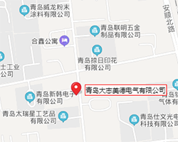
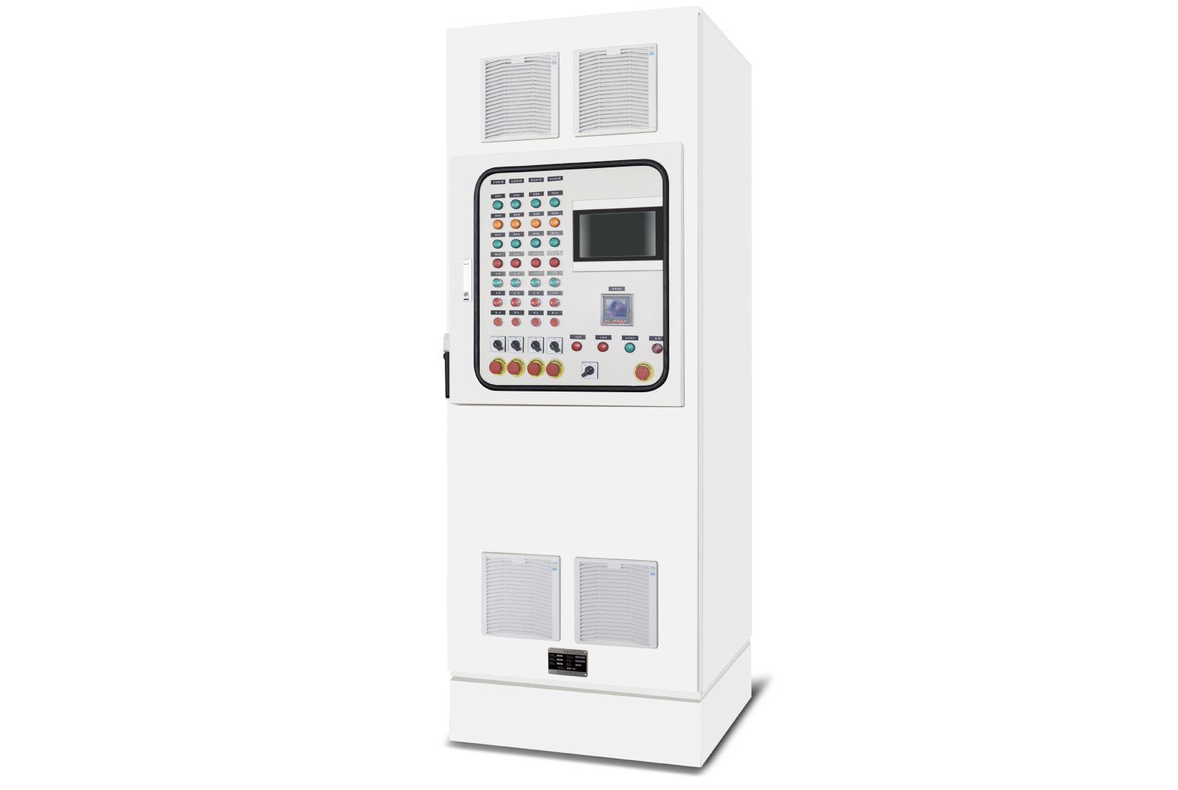
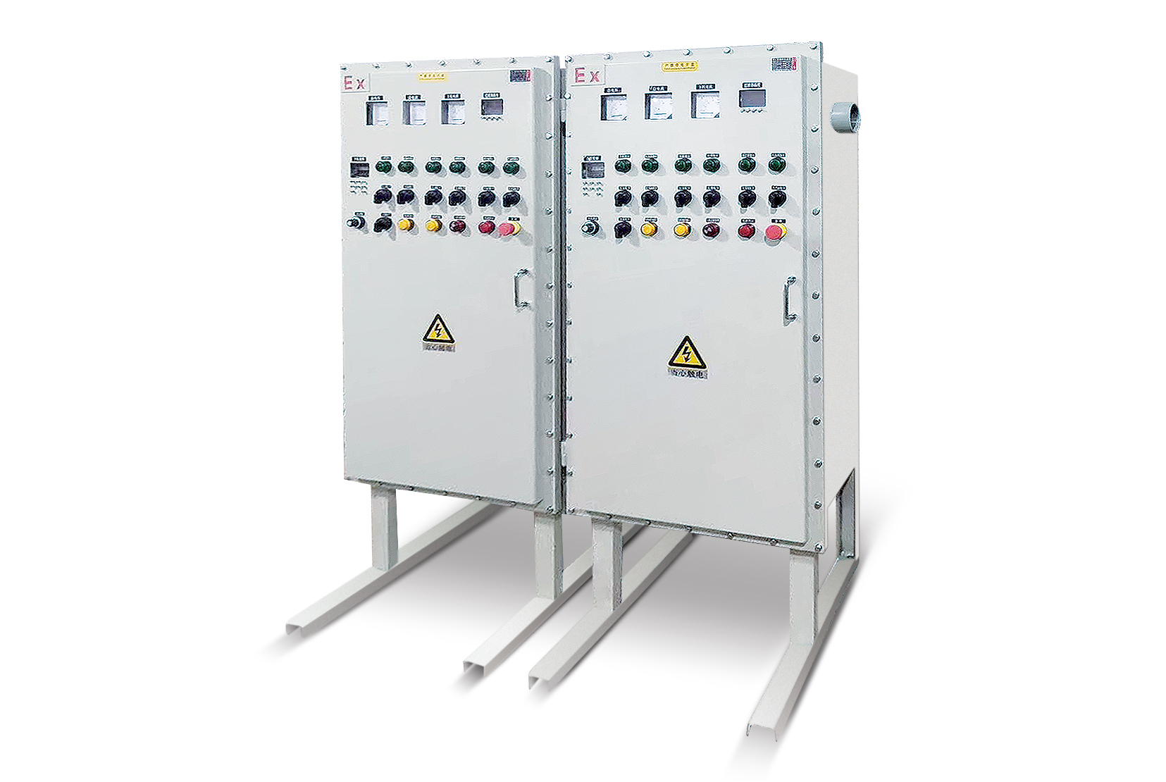
本装置是一种用于标准模件工厂组装(FBA)的组合式低压开关柜(以下称为本装置),本装置适用于交流50-60Hz、额定工作电压660V及以下的供电系统, MNS低压成套开关设备主要用于发电厂、变电所及工矿企业中接收、分配电能,实现控制、保护、监测、通讯等功能。适用行业包括轨道交通和电信、航空航天;主、副动力柜、配电柜;电动机供电和电动机控制中心;公用事业;电力系统;石油化工;船舶、石油钻井平台;市政供水及工矿企业;污水处理;商贸中心酒店等。
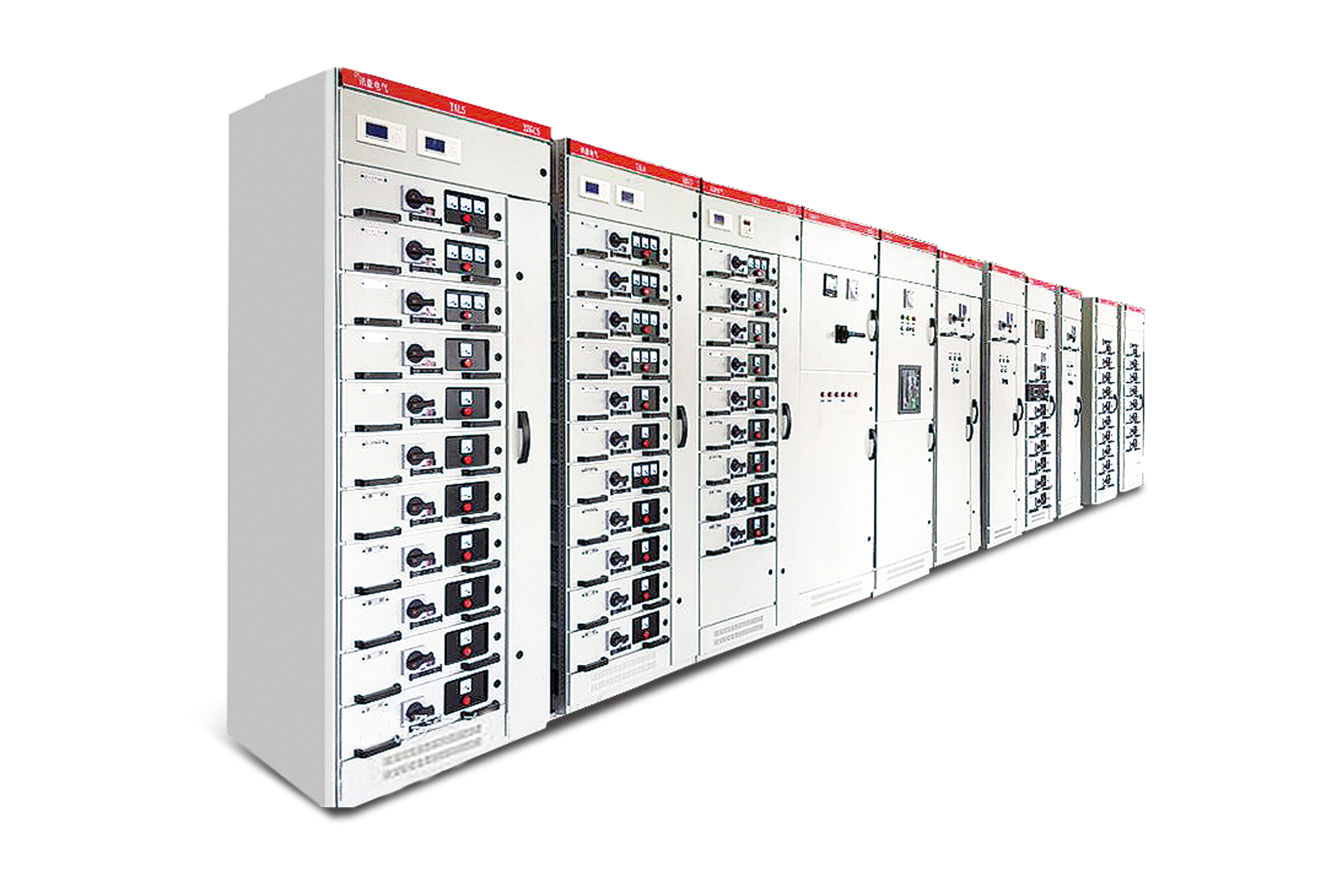
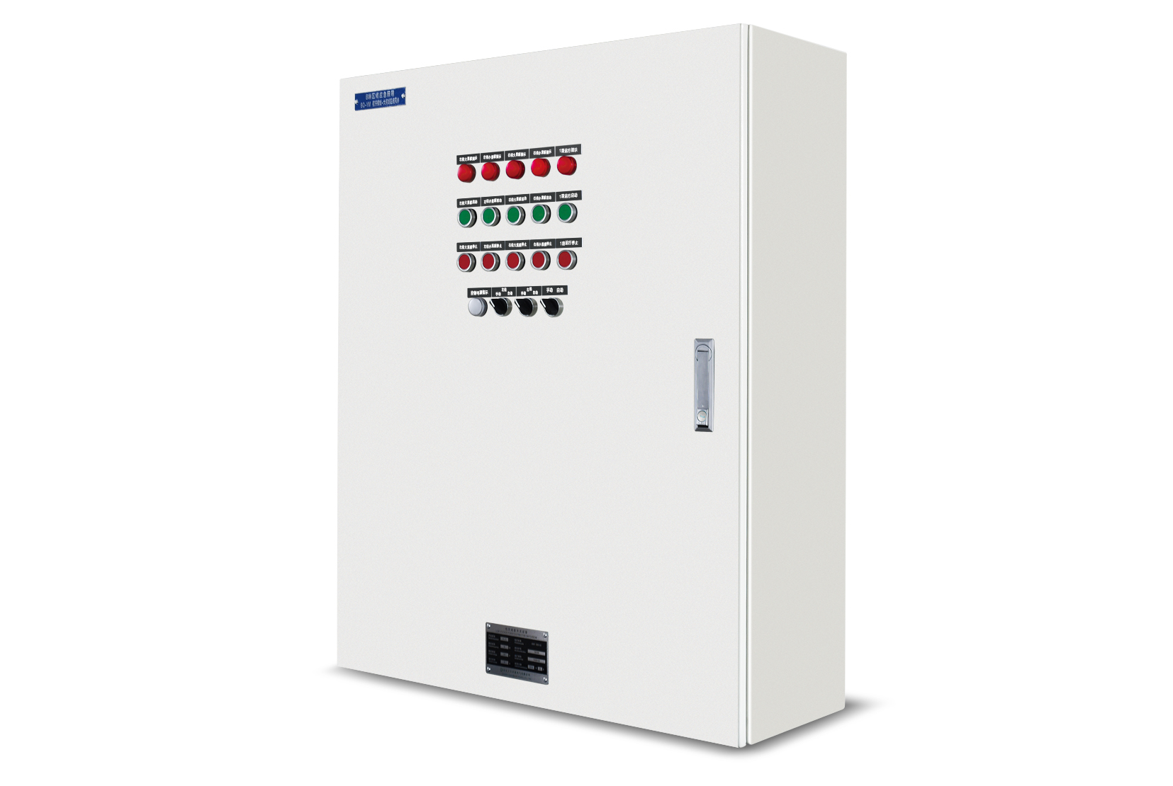
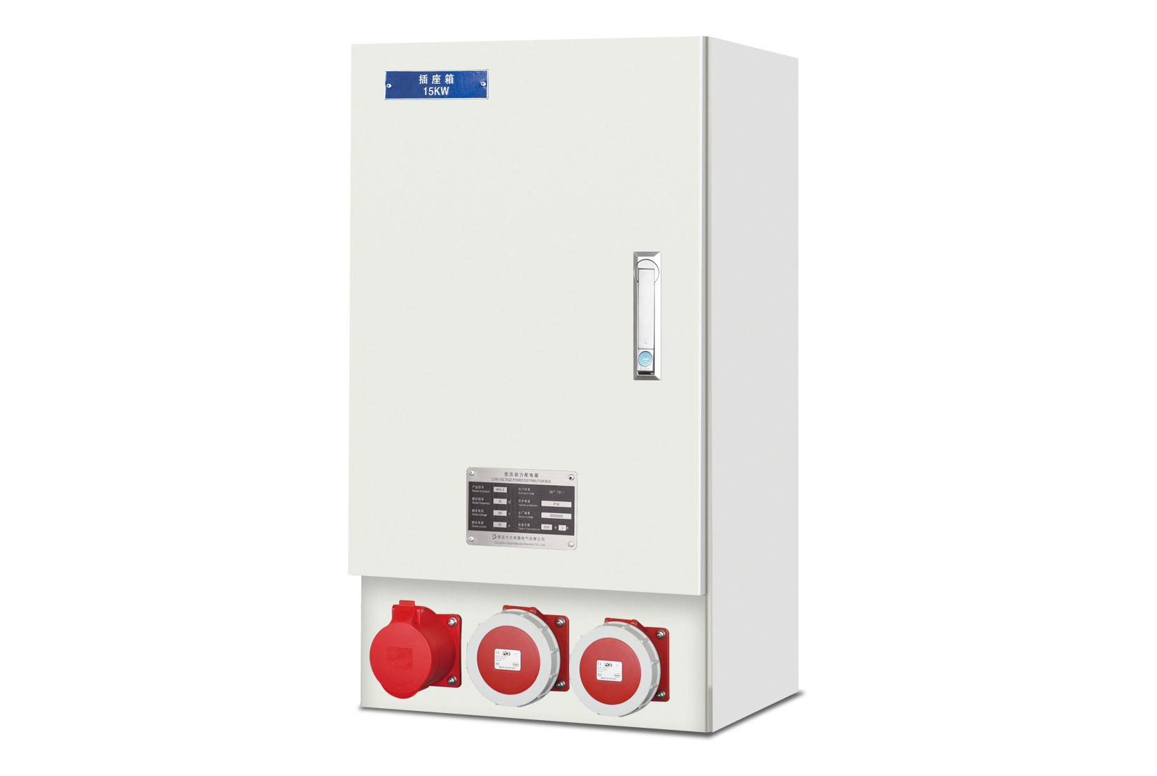
动力照明系统包括动力和照明两部分,动力系统的职能是向机电设备提供可靠的电力能源,照明系统为整条地铁线路的生活、工作、应急及疏散等全方位的照明设备供电,并对各设备实现智能化控制。动力照明配电箱以配电室内400V开关柜出线端为起点,为区域范围内所有动力照明设备供电。通过与BAS、FAS等相关专业的接口配合完成整个动照系统的自动控制。


热门关键词:
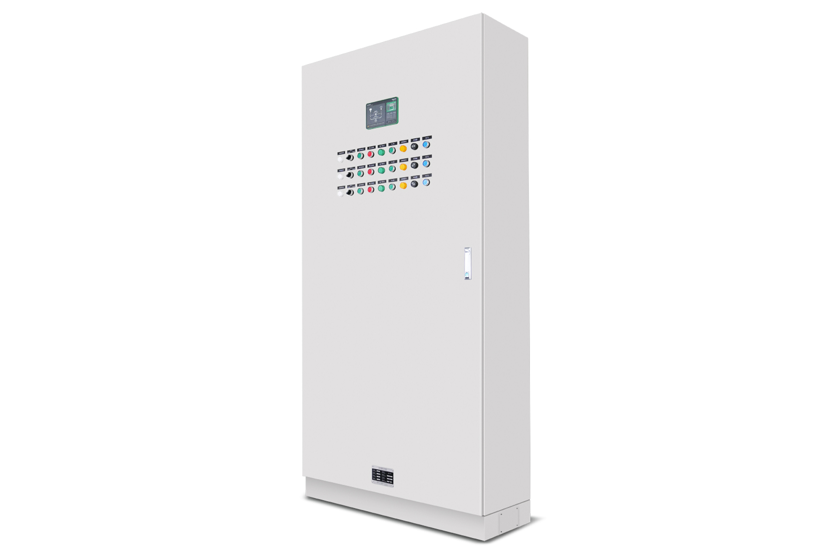
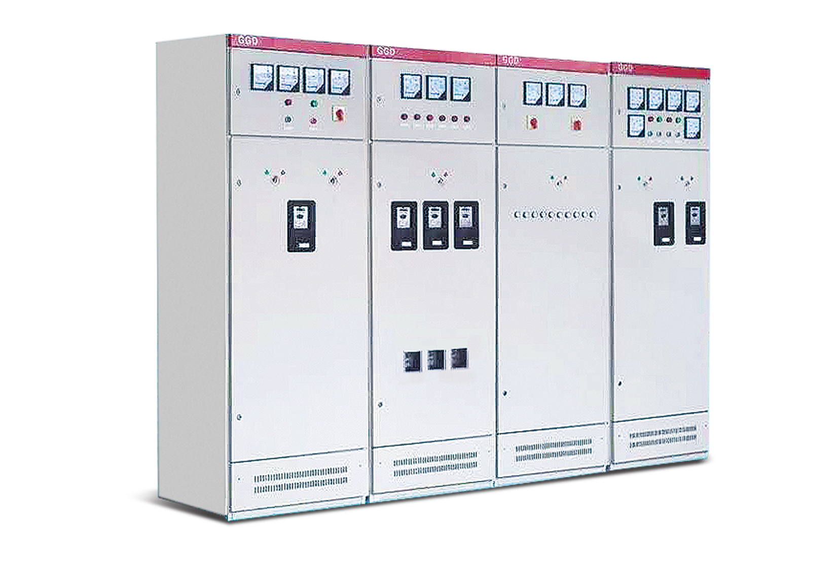
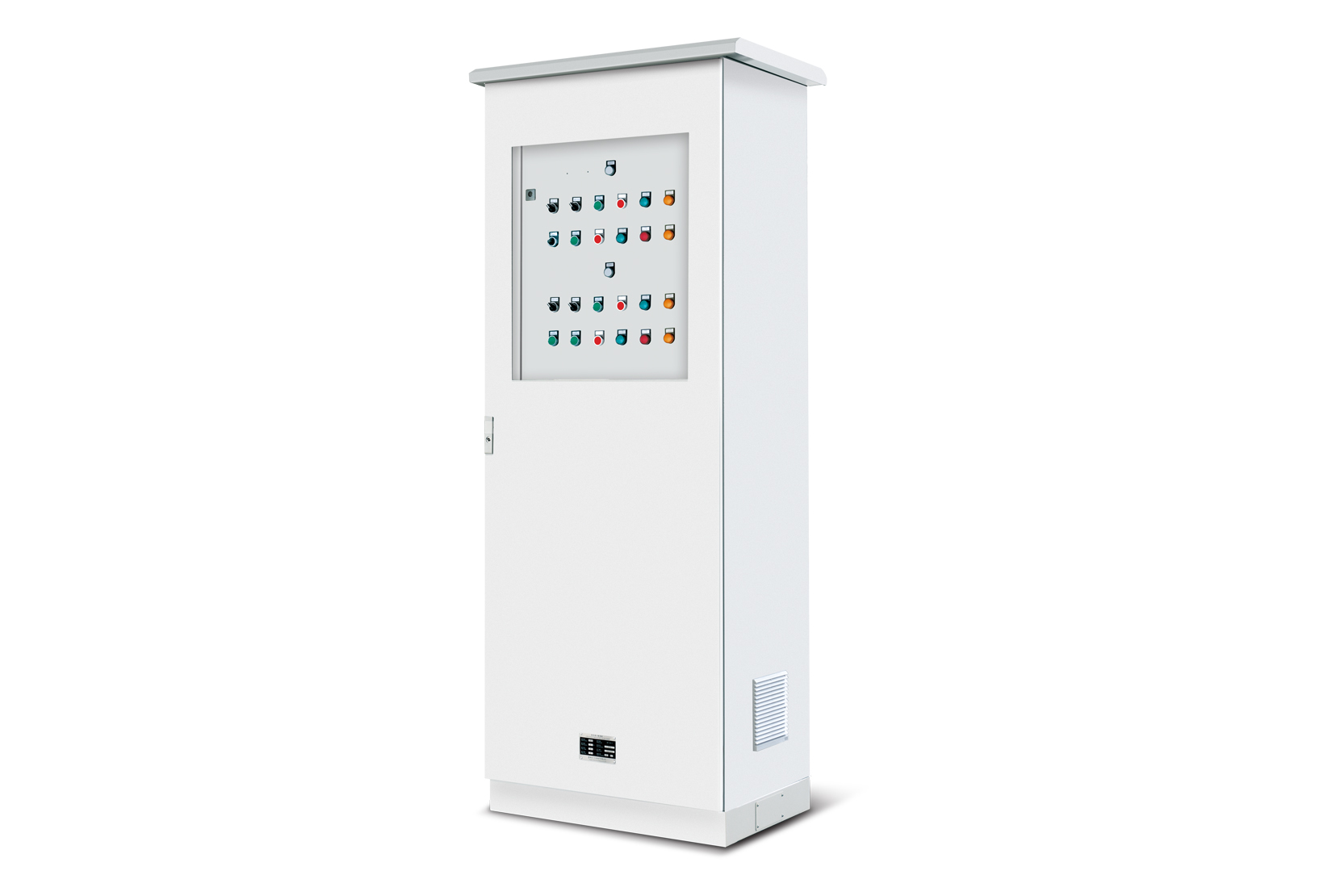
The dual power supply control cabinet is mainly composed of dual power supply automatic switching devices, which can switch automatically between the common power supply and the backup power supply accordingly, to ensure the reliability and continuity. It is widely used in high-rise buildings, power communication, industrial and mining enterprises, ship transportation and other important places that require uninterrupted power supply.
Environment
1.Ambient temperature: -5℃ to +40℃, average temperature within 24 hours ≤35℃;
2.Atmospheric conditions: The air should be clean. The relative humidity should not exceed 50% when the temperature is +40 ℃. Higher relative humidity is allowed when at a lower temperature, such as 90% at +20℃. However, condensation may occur occasionally when temperature changes;
3.The maximum altitude of the equipment installation site: 2000M;
4.The violent earthquake within 8 degrees;
5.Place without serious pollution, chemical corrosion or severe vibration.
Reference standards
1.GB/T7251.1-2013, Low-voltage switchgear and controlgear assemblies-Part 1: General rules;
2.GB/T7251.12-2013, Low-voltage switchgear and controlgear assemblies-Part 2: Power switchgear and controlgear assemblies;
3.IEC61439-1, Low-voltage switchgear and controlgear assemblies.
Basic technical parameters
Insulation resistance:500VDC, 大于100M
Insulation withstand voltage:2KVAC, 1min
Medium strength:1.5KVAC,1min
Impulse voltage:5KV,1.2/50us
Electromagnetic compatibility (refer to the corresponding items in GB/T 14598)
Electrostatic discharge: Level 4
Fast transient burst: Level 4
Damped oscillating wave: Level 3
Radiated electromagnetic field: Level 3
1.2/50-8/20us surge: Level 3
Power frequency magnetic field: Level 4
Mechanical behavior
Vibration: Refer to the standard GB/T 11287-2000 for severely registered vibration. The structure is damaged after the test.
Collision impact: Reference standard GB/T 14537-1993 Class I crash test.
Main Specifications
Rated input voltage: DC220V, DC110V, DC48V (±10%);
Threshold for voltage loss switching: 75% to 85% of rated voltage (can be set between 70% and 90%);
Maximum switching current: 100A (can be customized if more than 100A);
Signal output: 6 channels (can be field-programmed via a dedicated programming module or notebook);
Maximum system power consumption: 30W.
Ordering Notes
The following information should be provided when ordering:
1.The full model of the product (including the main circuit plan number and the auxiliary circuit plan number);
2.Combination sequence diagram of main circuit system;
3.Electrical schematic diagram of auxiliary circuit;
4.List of electrical components in the cabinet;
5.Other special requirements that are inconsistent with the normal use conditions of the product.